Microwave Temperature Profiler Related Patents
2000 January 13
Patent #1
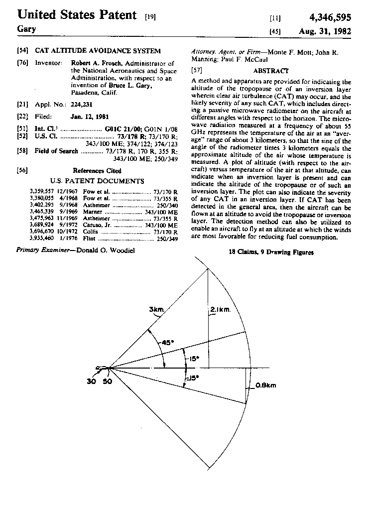
The following is page 1 from the patent for guiding aircraft to flight altitudes less prone to clear air turbulence using the MTP. A complete copy of the patent can be obtained by sending an e-mail request to me (given on the main web page).
Figure 1. Copy of first page of patent.
__________________________________________________________________________________________________
Patent #2
The following is page 1 from the patent for guiding aircraft to their optimum flight altitude using the MTP's temperature field to determine air density versus altitude. A complete copy of the patent can be obtained by sending an e-mail request to me (given on the main web page).
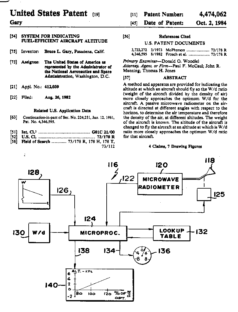
Figure 2. Copy of first page of patent.
__________________________________________________________________________________________________
Patent #3
The following appeared in NASA Tech Briefs, March 1992. A copy of the patent can be obtained by sending an e-mail request to me (given on the main web page).
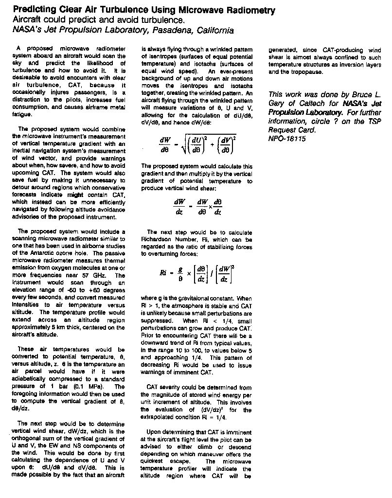
Figure 3. Copy of NASA Tech Briefs summary of patent.
_____________________________________________________________________________________________________
Patent #4
The following is a white paper describing a patent, submitted August 1999, that describes a method for predicting when engine intake air density changes will occur with sufficient warning to start a bypass baffle adjustment that will keep the shock wave at its desired location inside the engine, thus preventing compression loss and engine "unstart."
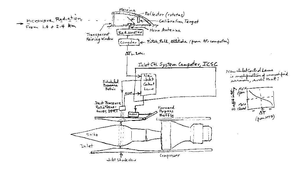
Figure 4. Drawing of components involved with patent #4.
The diagram, above, sshows the interface between the "microwave unstart radiometer" (MUR) and the engine's "forward bypass baffle" controls. The MUR can operate at 1 or 2 frequencies. The preferred arrangement is to employ the two local oscillator frequencies 58.8 and 57.2 Ghz with two identical mixer-preamplifier radiometers. The double-sideband radiometer will accept intermediate frequencies between 280 and 380 MHz. A stepper motor will rotate a reflector to compensate for pitch changes so as to maintain a horizon viewing direction. At intervals, such as once every 5 mintes, the reflector will rotate 180 degrees to direct the viewing area onto an ambient target, which will be used to perform a system gain calibration. The "transparent fairing window" will be made of a material not yet identified, which will have minimum absorption and reflection of incoming microwave radiation.
The incoming radiation will originate from distances that can be characterized by "applicable ranges" of 1.4 and 2.4 km (for an assumed flight altitude of 19 km). Measurements of the radiometer output will be converted to brightness temperature at each of the two frequencies every 1/3 second. A trend analysis for TB at both frequencies will be performed (to reduce the effects of stochastic noise, which will be approximately 0.18 K per 1/3-second reading), and a retrieval coefficient calculation will be made of air temperature versus range for the region 0 to 1.7 km, which corresponds to 0 to 2.0 seconds of flight time.
Thus, every 1/3 second the MUR computer will calculate a predicted time history of inlet air temperature for the next 2 seconds. A 1-second dT paramter will be used to represent a most likely change in temperature during the next second, and this will be conveyed to the aircraft's "Inlet Control System Computer" (ICSC).
The ICSC controls the fore/aft position of the "inlet spike" and the open/close setting of the "forward bypass baffle." The inlet shock wave must be positioned at the location indicated, and it's position is deduced by noting where the pressure against the inlet wall increases abruptly as the air passes a set of sensing points. A Duct Pressure Ratio Transducer combines pressure readings at these various inlet locations with static and dynamic pressures measured at a location outside the inlet, and these are converted to a set of pressure ratios suitable for deducing the shock wave location. The ICSC calculates a set of desired pressure ratios based on the aircraft's current pressure altitude, Mach number, pitch and yaw, and also based on a schedule of engine performance requirements for these conditions, and the ICSC transmits the desired pressure ratios to the Duct Pressure Ratio Transducer, DPRT.
The DPRT compares the measured pressure ratios with "desired" values from the ICS computer. The desired pressure ratios are calculated using "inlet control laws," which are prepared to assure proper engine performance. The ICSC "inlet control laws" for an aircraft with a MUR will be a modified version that allows for use of the MUR's dT input. The graph shows an example of the modification that will be necessary.
To illustrate with an example, when the MUR indicates that upcoming air will be warmer (less dense) than air presently entering the inlet, i.e., dT > 0, if no precautionary measures were taken the inlet shock wave would move aft, toward the compressor, when the warm air arrived. To prevent this from happening the forward baffle door should move to a more closed position as the warm air arrives. Thus, the New Inlet Control Laws will be a modified version of the previously-used Inlet Control Laws, such that a MUR-predicted warming shall produce a pressure ratio set corresponding to a shock wave location that is forward of the current one. Prior to the warm air's arrival, but after the MUR's dT input and the ICSC's command for a new desired pressure ratio set, the DPRT will generate a pressure ratio error that will be interpreted by the ICSC as a need to adjust the forward bypass baffle to a more closed position. As the forward bypass baffle begins to close, the warm air will begin to enter, and the inlet shock wave will remain in the desired position.
Return to CAT
Overview
Return to Resume
Page
This site opened: January, 13, 2000. Last Update: February 26, 2002